|
The Research & Development Notes
These notes contain the following chapters. Click to go directly to a chapter, or just scroll down.

Basic ECU Theory
To understand the idea of tweaking the Air Intake Temperature (AIT) Sensor, you first need to understand the basics of the Fuel Injection ECU (don't worry, I'll stick to the basics :-)
Any modern Fuel injection software consists of a basic fuel map plus a number of add-ons related to ambient conditions. Period.
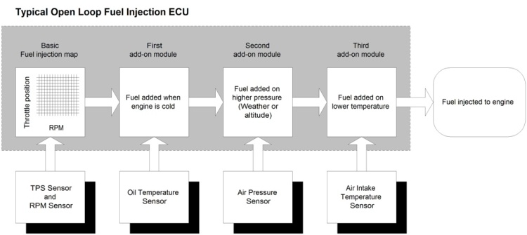
This is a schematic view of the ECU. You won't be able to actually see any of the modules inside the ECU – it's just software.
The basic fuel map is a grid of typical 12x12 or 15x15 lines. One axis is the throttle position sensor (TPS) - the amount of throttle you're applying, the other axis is RPM.
So, if the grid is 15x15 lines, we'll have 225 crossings of throttle position and RPM. For each crossing, the factory programmers have decided on an injection amount. Got it ? Depending of the amount of throttle you apply and the RPM of the engine, the basic amount of fuel injected is determined here.
Unfortunately, this is not sufficient to inject the correct mixture. We must consider temperature and air pressure too.
First add-on is oil temperature. The idea is to determine if the engine is cold or at running temperature. At zero degrees Celcius, you'll see a fuel add-on amount of aprox. 35%. This amount will be decreasing to 0% at about 50 degrees C. This part is about the warm up phase of the engine – we are not changing anything here.
Next add-on is the Air Pressure Sensor, which will tell the ECU if the weather is changing or if you are going up the mountains. Your ECU will maintain the correct fuel/air ratio at the new higher altitude. The reduced amount of air available at a higher altitude will require a reduced amount of fuel to maintain the correct ratio. This is all taken care of by the Air Pressure Sensor. No worries.
The add-on for the Air Intake Temperature will read the AIT Sensor and make the mixture richer as the weather gets colder. The amount of extra fuel needed to compensate a certain temperature drop will be the same for all engines, as this relates to the variation in density of air molecules as the temperature is changing.
This may sound very technical, but the good thing is that we know that any fuel injection ECU will richen the mixture 3% when the temperature drops 10 degrees Celsius. This is the interesting part, so remember it for the next chapter.
If the factory engineer did his job properly, we now have a qualified estimate of the correct amount of fuel to inject to the engine, under all combinations of load, rpm's, temperature and altitude/weather.
But it's important to understand that this setup provides no feedback from the engine if the estimated amount of fuel injected was right or wrong. This is called Open Loop Operation
Tolerances of different components, adjustment of Throttle Position Sensor or fuel pump pressure, wear in the injector nozzles etc. etc, will all cause the mixture to differ slightly.
So it's nice to have some kind of feedback from the engine, to tell if the injected mixture is correct or not.
It's done by placing a Lambda Sensor in the exhaust pipe (Also known as Oxygen Sensor or O2 Sensor). The sensor will provide feedback to the ECU if the injected mixture was too rich or too lean. This feedback is entered in another add-on module in the ECU where the the final adjustments are taking place. So if the Lambda Sensor measures traces of rich mixture, the ECU will make the mixture a little leaner. This is Closed Loop Operation.
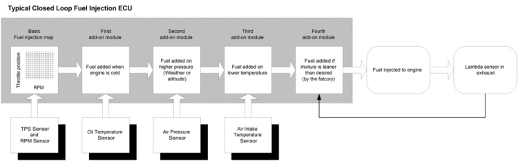
If the Lambda sensor feedback could work without a delay, we wouldn't need the basic fuel map and the other add-ons.
Unfortunately, there's a certain signal feedback delay, and the Lambda Sensor feedback can be nothing but an add on module to the open loop ECU.
To have closed loop operation function properly, it requires a base map that is correct within 20%.
Most newer bikes have ECU's with Closed Loop programming – Check if you have the Lambda sensor in the exhaust header pipe.
Basic Resistor Tuning
Pay attention now – This is how it works.
If we are able to make the ECU think the air temperature is 20 degrees Celsius lower than the actual temperature, it will raise the entire fuel map by 6%. This is the sweet spot we're aiming for to achieve the positive effects mentioned earlier.
You may ask why the factory's engineers didn't add a little more fuel if it's such a good idea ?
These guys are certainly not stupid, and they would love to richen the mixture a little for power and rideability – but they are not allowed to do this due to legal and environmental requirements.
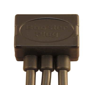
That's why there's a market for Power Commanders, Tune Boy, Rapid Bike, Power FRK, etc. and of course the BoosterPlug :-)
The simple way to richen up the mixture is to add a fixed resistor in serial connection with the Air Intake Temperature Sensor to increase the resistance as measured by the ECU.
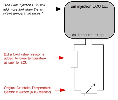
The Air Intake Temperature Sensor is always a NTC resistor (NTC is short for "Negative Temperature Coefficient", which means that the electrical resistance will drop as the temperature rises).

Take a look at the chart above. Top line is the temperature (Degrees Celsius), and the second line is the resistance of the AIT. The ECU is programmed with the knowledge that 5283 ohms resistance from the AIT input means that it is 20 degrees Celsius outside, and will adjust the mixture accordingly.
Note that the NTC resistance values stated are just an example. I'm not stating real values for a specific bike here, but of course the correct resistance values for each bike are used to calculate the BoosterPlug.
You should know that there are plenty of different NTC's on different bikes.
Bottom line shows the typical modification with a fixed resistor in serial connection with the AIT. In this example I've used a 10.000 ohms resistor.
The ECU will now measure 15283 ohms at 20 degrees Celsius. (5283 ohms from the AIT and 10k ohms from the extra resistor). But as the pre-programmed ECU calculates the temperature from the middle line of the chart, it will “think” the temperature is around 0 degrees (15232 ohms is 0 degrees C.)
The mixture injected to the engine will therefore be 6% richer, and we have achieved our goal.
It's a brilliant and simple way to richen up the mixture, but you must understand that it will work differently on Open Loop and Closed Loop ECU's (See previous chapter for an explanation of Open Loop and Closed Loop operation).
If you don't know whether your bike runs Open Loop or Closed Loop, check if you have an Lambda (O2) sensor in the exhaust. Only Closed Loop bikes have this sensor installed.
On early fuel injected bikes (No Closed Loop operation) the BoosterPlug will add 6% of fuel to the entire fuel map (6% is just the example from above - it can be something else with another resistor). This means that if your current fuel consumption is 5.0 liters per 100 km, it will be raised to 5.3 liters. A small fee to pay for an improvement you will enjoy every minute on your ride.
If your bike is from 2006 or newer, it will be featuring Closed Loop operation, and then the resistor tuning idea is even smarter. The lambda sensor will try to adjust the mixture back to the pre-programmed level, but the time delay mentioned earlier will work to our advantage.
In conditions where you maintain constant RPM and throttle opening while cruising on the open roads, the feedback from the lambda sensor will adjust the mixture back to the original level, and our small tuning device will sit idle and wait for something to happen. This is fine – you don't need the richer mixture at level speed.
As soon as RPM or throttle opening moves, the fuel map will shift horizontally or vertically on the 15 x 15 grid, and the lambda sensor feedback will be temporarily disabled. This means that the ECU runs open loop for a short period every time we change RPM or throttle, and the enrichment from the AIT sensor modification kicks in exactly at this point.
As the enrichment will only be effective under these conditions, the extra fuel consumption will only be aprox. One third of the 6%, so if your usual fuel consumption was 5.0 liter / 100 km, it will now be 5.1 liter. Still while maintaining all the positive effects.
Bloody marvelous job for a small resistor :-)
But (There's always a “But”) – actually we only almost achieved our goal, and the resistor tuning idea certainly needs some development to be brilliant. Even though both the creative DIY biker and the Snake Oil salesman use this setup, there's a huge disadvantage that will eliminate the positive effect.
The Problem
The problem using a serial resistor is that the amount of added mixture will vary a lot with changes in ambient temperature, and this is certainly not what we want.
This is caused by the non-linear resistance curve of the AIT Sensor, which is not easily manipulated correctly.
Take a look at the chart from the last chapter again.
At 20 degrees Celsius, the ECU will measure 15283 ohms and “think” that the ambient temperature is around zero degrees Celsius. We have now cheated the ECU to think the air temperature is 20 degrees lower, and it will add 6% extra fuel. Great – just what we want.
But on a hot day at 40 degrees Celsius, things are looking a lot different. The ECU will now measure 11837 ohms, and “think” the temperature is +7 degrees Celsius. This is a difference of 33 degrees, and the ECU will now add 10% of extra fuel. This is too much fuel and your bike will now feel “wooly” and imprecise.
If you're riding in the cold season and the temperature hits 0 degrees Celsius, the calculation will look like this: The ECU will measure 25232 ohms and translate it to a temperature of -12 degrees. With a difference of 12 degrees, the ECU will only add 3.6% fuel. The positive effects you experienced at 20 degrees Celsius are almost gone.
The chart below shows how much the serial resistor trick will lower the ambient temperature (as seen by the ECU)

This means that within the temperature range where people actually consider riding their bikes, the serial resistor will add from 3% to 10% fuel. Not exactly the high tech solution some of the Scammers are promoting.
The graph in the chart below shows the poor performance of the serial resistor.
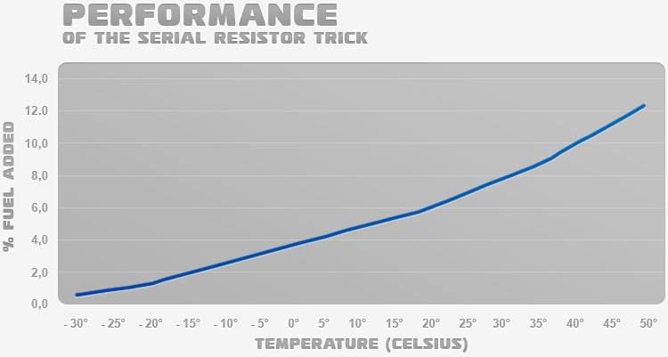
Also it becomes clear why discussion forums on the Internet contain long discussions, with very different opinions, about the right size of the resistor to add for a specific bike. People around the globe are simply operating their bikes in different climates, so they need different resistors to lower the temperature around 20 degree = 6% more fuel)
After a lot of calculating and testing, I managed to develop a device that will eliminate this problem – if you're still with me, read on to see the Solution.
The Solution
Once again, I'll start with the chart from the previous page.
It's clear that the solution provided by the serial resistor trick is only useful if the ambient temperature is always the same.
We obviously want a setup that is able to lower the temperature 20 degrees Celsius, as seen by the ECU. Regardless if the ambient temperature is 0 or 30 degrees Celsius.
Unfortunately, there's no possible way of obtaining this with ordinary resistors. No matter the size of your resistors or how you combine them in serial and/or parallel connection with the AIT sensor.
The non-linear resistance/temperature curve of the NTC resistor makes it impossible.
It's important to mention that the AIT input will do absolutely nothing else than read the total resistance in the two wires of the input. You'll hear the Snake Oil Salesman claims to use microprocessors and read RPM on the AIT input. This is plain bullshit.
Hang on – I'm getting at it now :-)
I got the idea to level out the dependence of ambient temperature, by using yet another NTC resistor in a serial/parallel connection with a few fixed resistors.
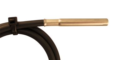
The second NTC sensor will have to measure approx. the same temperature as the AIT sensor, so it must be installed where its not affected by engine heat.
This is important as the temperature under the shielding can be 20 degrees Celsius higher than the outside temperature because the area is influenced by the hot engine.
That's why I put the second NTC sensor on an external cable. - This is the only way to obtain a stable output.
NTC's have rather different characteristics depending of brand (They really are very different.....), and it was hard to find the right one. I spend a lot of time on calculations and testing of prototypes and finally I managed to stabilize the output in all real life temperatures situations. The BoosterPlug was born !
 The IMPORTANT bit ! - The BoosterPlug is the only Plug and Play device that will keep the enrichment correct and stable under different temperature conditions.
Take a look at this chart to see the performance of the BoosterPlug – I'm pretty proud of it :-)

The BoosterPlug will make the ECU think the ambient temperature is 20 degrees Celsius (+/- one degree) lower than actual, in a temperature range from -23 to + 37 degrees Celsius.
So with the BoosterPlug, you will get a 6% richer mixture regardless of the temperature conditions you're riding in.
The Graph shows the performance of the BoosterPlug.
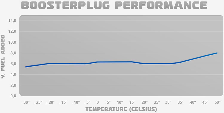
You'll see that the line tends to drift off at extremely high temperatures, and that its not completely horizontal in normal riding temperatures. But this is really insignificant and you'll never notice it.
In hot climates with temperatures above 40 degrees Celsius, the thermal stress on the engine is extremely high, and the slightly richer air/fuel ratio in high temperatures will help to keep the combustion temperatures down. Your engine will thank you for it !
This is as good as it gets with the use of passive (no CPU brain) components - and it's quite good actually :-)
|